Spent Fuel Storage
Spent Fuel Storage Pool and Spent Fuel Cooling System
All nuclear plants have storage pools for spent fuel. These pools are typically 40 or more feet deep. In the bottom 14 feet are storage racks designed to hold fuel assemblies removed from the reactor. In many countries, the fuel assemblies, after being in the reactor for 3 to 6 years, are stored underwater for 10 to 20 years. The water serves 2 purposes:
| Studies have shown that, in actuality, only about 8 feet of water is
needed to keep radiation levels below acceptable levels. 24 feet provides extra margin and
allows fuel assemblies to be raised and moved without increasing the radiation exposure
for the personnel in the area. The decay heat rate produced by fuel assemblies removed from a reactor initially decreases by a factor of one-half every twelve days, then by a factor a one-half every year. Please click to see figures illustrating the reduction in heat and radiation levels for spent fuel assemblies. |
|
| Photo by J.A. Gonyeau |
The CANDU spent fuel storage concept is similar, except that the small fuel assemblies are removed from the reactor horizontally and are stored that way in the spent fuel pool.
Generally the storage pools have redundant heat exchangers and pumps for cooling the pool. Pool temperature is monitored and varies between 90F and 120F. The spent fuel cooling system is, in turn, by a component cooling system. Usually, a number of additional backup sources of water are available for use if the primary method of cooling is unavailable - including large storage tanks, demineralized water, reactor makeup water, and finally, firemain water.
|
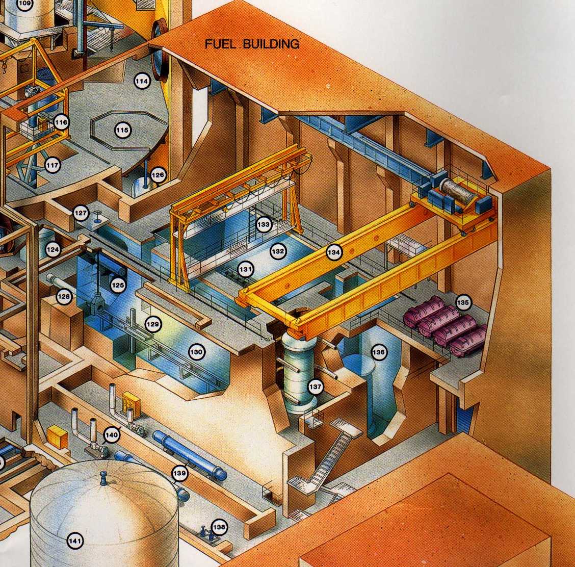
The spent fuel cooling pool can also be connected to the containment during refueling outages so that spent fuel, removed from the reactor, may be transferred for storage in racks in the pool. (Click for overview graphic - detailed graphic). For the detailed graphic an explanation of the numbered components in given on the Fuel Building page. In some cases, these operations are controlled manually. In others they may be controlled from a control panel as shown to the left. |
| Photo by J.A. Gonyeau |
Dry Cask Spent Fuel Storage
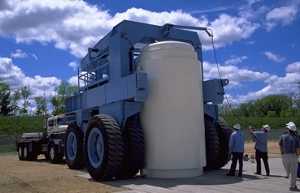 |
After 10 or more years, the radiation and decay heat levels are low enough that the fuel assemblies may be stored in large casks which can be cooled by air passing on the outside. An example of such a cask is shown below. Such casks typically hold 24 to 40 fuel assemblies. The casks have double metal ring seals and are bolted to ensure radioactive material release should not be able to occur. The cask shown is about 17 feet high and 9 feet across. Pressurized helium gas is used inside the cask with a to promote heat removal from the fuel assemblies to the cask wall. Air on the outside removes the heat. Pressure inside the casks and temperature on the outside is monitored. See the dry cask storage page for or additional photos of dry cask storage facility. |
| Photo courtesy NSP |
Spent Fuel Storage - Alternative Methods
Ontario Hydro, at the Pickering units east of Toronto, has built a separate building on the plant site to accommodate the spent fuel storage canisters (smaller than the one shown above since the CANDU design fuel rods are smaller than the PWR fuel assemblies). This facility is used after the spent fuel has spent years cooling in a storage pool before transfer to this facility.
 |
The sloped roof storage building is located on the right side of the photo. Storage canisters for spent fuel rods would be stored in the building. The horizontal containers shown in the left side foreground above are used for coolant tubes removed from the Pickering reactors when these tubes were upgraded. |
| Photo by J.A. Gonyeau |
Spent Fuel Storage - Still More Methods
At some facilities, the 2 designs illustrated in the photo and graphic below are used.
|
|
Courtesy Pacific Nuclear |
Courtesy Power Engineering |
Offsite Storage Concepts
With the continued delay by the Department of Energy, other alternatives, e.g. storage in the Western United States, are being pursued. See Current Hot Topics for information on the Goshute and Wyoming options being considered.
Copyright © 1996-2004. Joseph Gonyeau, P.E.. The Virtual Nuclear Tourist. All rights reserved. Revised: March 15, 2001.