Containment -
Bird's Eye View
Overview
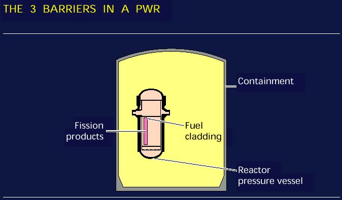
A key principle in the design of the nuclear plant is defense in depth. There are
intended to be 3 barriers between the radioactive fission products and the public in order
to reduce the likelihood of radioactive releases. These 3 barriers are - the fuel
cladding, the reactor coolant piping, and the containment. Two graphics - by the
NRC and EdF - illustrate this
concept..
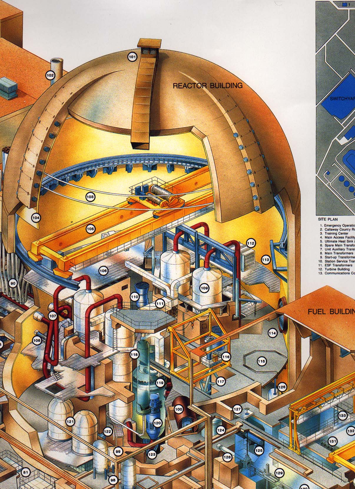
The containment is a large steel building, usually with a hemispherical dome.
Containments are often not visible since they are usually surrounded by a steel or
concrete building that provides additional boundaries and aesthetically pleasing designs.
The containment is capable of sustaining high internal pressures. Design is in the
range of 45 to 60 psig, however, much higher pressures, even exceeding 100 psig may be
sustained. Ice condenser containments are usually designed for about 12 psig. In either
case, the containment is designed for a double ended rupture of the largest diameter pipe
in the structure. These pipes are usually 3 feet in diameter.
The containment houses the reactor, reactor cooling or recirculation system and pumps.
For PWRs, the pressurizer is also in the containment.
Containments have fans or chiller units for cooling during normal conditions and in the
unlikely event of an accident. To provide additional cooling and pressure suppression,
several ring headers are mounted in the uppermost part of the containment. These ring
headers are used to spray water (often borated) to reduce pressure.
Below the containment basement, there are sumps that can be used during accident
conditions. The sumps can be routed to cooling systems so that the fluid may be
recirculated and cooled. A grating system is installed over the containment sump (click for
photo of sump) to prevent materials from being sucked into the cooling system, usually
called the Residual Heat Removal system.
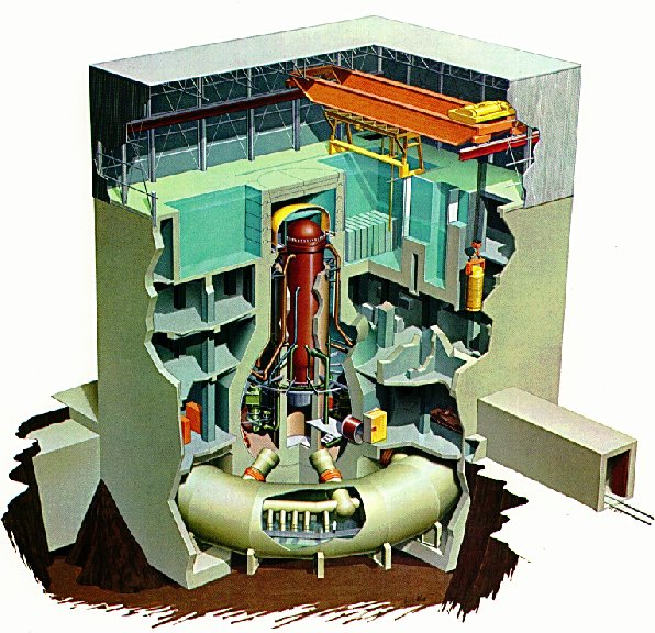
- Several Birds-eye views of the inside
-
- This photo provides a birds-eye view from the top of a containment.
 |
Using the center of the photo as a reference: The refueling pool is
directly below. During a refueling the head is removed from the reactor and is stored
within the containment. The upper internals are removed and stored underwater in the
refueling pool.
The crane (orange-color) is used to move new and old fuel. Directly below is the
reactor.
Steam generators can be seen in the lower right and just to the upper right from the
center.
Ventilation ducts can be seen along the wall of the containment.
The reactor coolant pumps, pressurizer, and emergency core cooling accumulators are
also found in the containment. |
| Photo (of photo at a plant) by J.A. Gonyeau |
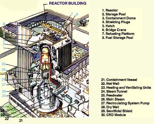
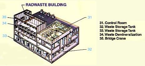
The following equipment is located within the
containment (PWR) or
drywell or
drywell/wetwell and
radwaste building (BWR). Typical components
located in these buildings are:
Component Name |
Component Name |
| Unit Vent |
Equipment Hatch Lifting Gear |
| Auxiliary Boiler Stack |
Reactor Head Decontamination
& Storage Area |
| Containment Spray
header |
Refueling Machine |
| Steel Liner |
Internals Lifting Rig |
| Polar Crane |
Pressurizer |
| Laydown Area |
Reactor |
| Main Steam Lines |
Reactor Cooling Pumps |
| Main Feedwater Pipes |
Accumulators |
| Steam Generators |
Reactor Coolant Pump Motor
Oil Collection Tank |
| Hydrogen Mixing Fans |
Incore Instrumentation |
| Control Rod Drive Mechanism
Fans & Plenums |
Upper Internals Storage
Stand |
| Containment Coolers |
Reactor Coolant Drain Tank |
| Equipment Hatch Lifting Gear |
Pressurizer Relief Tank |
The
refueling operations page links to photos and graphics showing
equipment and activities in a containment during a refueling.
Copyright © 1996-2004. Joseph
Gonyeau, P.E.. The Virtual Nuclear
Tourist. All rights reserved. Revised: December 8, 2005.