Emergency Core Cooling Systems (ECCS)
All nuclear power plants have some form of emergency makeup water system in the event that normal makeup is lost and a major break occurs in the reactor cooling system. These emergency systems are called such names as - High Pressure Coolant or Safety Injection, Low Pressure Coolant or Safety Injection, Reactor Core Injection Cooling.
There are two phases considered - (1) the Injection phase when the pumps take a suction from a large tank and pump that water into the reactor cooling system or reactor, and (2) the Recirculation phase when the pumps take a suction from the containment sump after all of the water has been pumped into the containment.
The Emergency Core Cooling Systems have 1 major function:
The Emergency Core Cooling Systems, in some plants may have a second major function:
Major Components
Water supplies (tanks), pumps, interconnecting piping
|
Containment sump at a PWR. Note the grillwork sized to keep loose materials from getting to the suction of the low pressure ECCS pumps during the recovery phase following the postulated loss of coolant accident. |
| Photo by J.A. Gonyeau | |
Power Sources
Emergency makeup or cooling pumps are usually motor-driven. In some cases, steam turbine-driven pumps are used (e.g. in the case of BWR systems HPCI (High Pressure Coolant Injection). For the motor-driven pumps, power may be received from diesel generators if power is lost from the normal power supply.
Sample ECCS System Drawings
A typical high head safety injection system is illustrated below.
A typical low head safety injection system (sometimes called RHR - residual heat removal) is illustrated below.
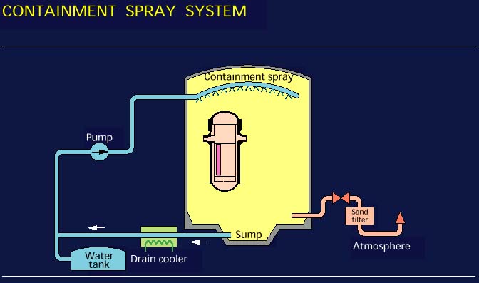
For a simple illustration showing the accumulators, low pressure and high pressure safety injection pump flow paths, an EdF drawing nicely illustrates the paths from the storage (or water tank in the drawing) to the reactor cooling system. In some plants the drain cooler is located between the RHR (or LPSI) pumps and the containment. The containment spray pumps shown in the EdF figure are part of the containment suppression systems. These pumps may be aligned to take a suction from the LPSI system to spray recirculated water (after cooling) back into the spray headers in containment).
Copyright © 1996-2006. The Virtual Nuclear Tourist. All rights reserved. Revised: January 4, 2006.