|
|
| Courtesy Sargent & Lundy / Power Engineering | |
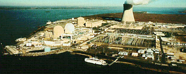
| Public Service Electric and Gas' Salem - Hope Creek facility near Hancocks Bridge, New Jersey. Salem, in the foreground, has 2 Westinghouse 4 Loop PWR units. In the background is the single General Electric BWR-4 Hope Creek unit. Salem 1 and 2 A number of simplified diagrams illustrate the the design of each Salem pressurized water reactor unit (courtesy Westinghouse) In each reactor, 193 fuel assemblies of the 17x17 design are used with 264 fuel rods per assembly. The containment is a large steel structure rated at 47 psi pressure.Each reactor coolant loop has 1 U-tube vertical steam generator and 1 reactor coolant pump. Each unit has a pressurizer connected to one of the 4 loops. Normal makeup water is provided by 1 of 3 Chemical and Volume Control System charging pumps. A smaller positive displacement pump is rated at 98 gpm and 2510 psi. The 2 centrifugal charging pumps, each rated at 150 gpm and 2510 psi double as the emergency high head safety injection system pumps. Their shutoff head is 2565 psi. On the non-radioactive secondary side of the steam generators, condensate-feedwater is supplied by 3 condensate pumps (693 psi) and 2 turbine-driven feedwater pumps which move the water from the condenser to the steam generators. Pressure and temperature are raised from vacuum and 90F to 1100 psi and 425 F. Emergency equipment for each unit include:
Emergency water sources include:
For detailed information, refer to the NRC Plant Information Books for Salem 1 / 2 Hope Creek The 1067 MWe BWR-4 Hope Creek unit has a Mark I torus and drywell type of containment. Sample photos of the typical BWR are provided. For detailed information, refer to the NRC Plant Information Books for Hope Creek 1 |
|
