Courtesy Leibstadt NPP
Turbines and Support Systems
All power plants - gas, coal, nuclear, hydro use turbines to drive the generator. In many parts of the world, a plant will have 2 turbines of 1/2 full load, rather than a single unit as is common in the United States.
The Turbine has one major function:
- Convert the energy from the high pressure steam to mechanical energy in the form of shaft rotation so that the generator will turn.
This conversion is done in two (2) stages - first in a smaller High Pressure Turbine, and after passing through the moisture separator, then in 2 or more large Low Pressure Turbines.
The Turbine Support Systems have the following functions:
- Control the amount of steam admitted to the turbine
- Lubricate the generator
- Keep the steam inside the turbine
- Protect the turbine in the case of a fault (electrical or mechanical)
The Moisture Separator has one function:
- Remove moisture from the steam leaving the high pressure turbine before admitting the steam to the low pressure turbines.
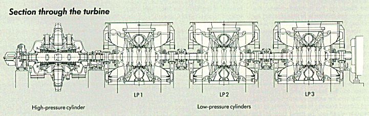
Major Components
The figure below illustrates the arrangement of the high pressure and low pressure turbines (called cylinders in the diagram). Steam is admitted in the center of each of the turbines, then expands out through the sets of blades. Often there are stationary blades which act as nozzles to direct the steam flow onto the moving blades.
|
Courtesy Leibstadt NPP |
Turbine Blading
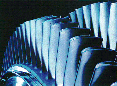 |
This photo illustrates the shape of the movable blades that the steam impinges on to cause movement. |
| Courtesy Siemens |
High and Low Pressure Turbines
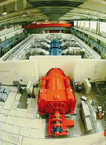 |
The three stages of the low pressure turbine are easily visible in this photo. At the far end is the high pressure turbine, barely visible because it is very small compared to the low pressure units. |
| Courtesy Leibstadt NPP | |
Hydraulic Control Valve Systems
Oil operated valves are used to regulate the amount of steam admitted to the turbine. Prior to the high pressure turbine, there are Stop Valves followed by Control Valves. Each steam supply line may have one stop valve with one or two control valves. Sometimes the control valves are referred to as regulating or poppet valves. The opening of the valves is based on electrical, instrumented, or digital sensing circuits that determine the proper amount of steam to provide.
Lubricating Oil Systems
 |
An oil system is used for lubricating the bearings on the turbine, much like the oil system in a car. Another oil system is used to keep the hydrogen in the generator. This oil is also cooled by the Service Water System. |
| Photo by J.A. Gonyeau |
Fire Protection System
Sometimes plants will have systems that will sense a fire. Upon receiving an alarm, the operator could decide whether to initiate a deluge system that will release water onto the turbine bearings to prevent an oil fire.
Moisture Separator
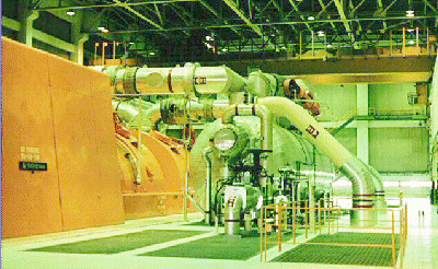 |
The moisture separator is the aluminum covered cylindrical vessel shown in the middle of this photo. Steam from the high pressure turbine comes from the right through pipes coming from the floor. The moisture-free steam the leaves via a large pipe at the top to go to the low pressure units. |
| Photo by J.A. Gonyeau |
Bearing
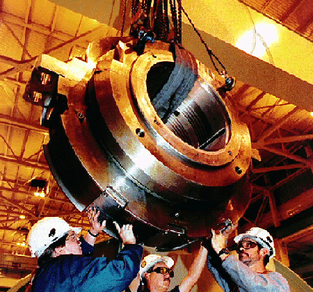 |
Photo showing a bearing removed from a turbine. The bearing supports the shaft. There are 2 bearings for each high and low pressure turbine unit. The bearing vibration and temperature are monitored continuously during plant operation. |
| Courtesy Nuclear News |
Copyright © 1996-2011. Virtual Nuclear Tourist. All rights reserved. Revised: Saturday April 02, 2011