Containment Pressure Control Methods
Functions
There are several methods used to control containment pressure during severe postulated accidents involving a loss of coolant from the nuclear plant's reactor coolant system. These are:
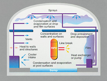
The single function of these systems in to remove the heat and reduce the pressure in the containment building during a postulated accident. The design pressure is about 60 pounds per square inch (psi) , although actually pressures over 100 psi could likely be tolerated.
The figure below illustrates the processes which reduce temperature and pressure in the containment in the event of a postulated reactor coolant or reactor vessel major leakage. The operation of spray and fan coolers systems are illustrated.
Graphic courtesy EPRI
Major Components
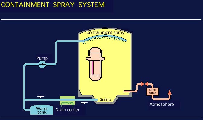
The Containment Spray system uses pumps to spray down the containment. These pumps take a suction from a large storage tank (usually over 200,000 gallons). Refer to the simplified EdF Containment Spray illustration for typical flow path design. The system pumps to several spray headers in the top of the containment. This diagram also shows the sand filter only used in the Framatome design. Please note that you need Adobe Acrobat to view this drawing.
The Containment Fan Cooler System uses fan coolers with large radiators cooled by the Ultimate Heat Sink or Safety Related Service Water System.
The Ice Condenser system, as used at the Sequoyah, McGuire, and DC Cook plants, maintain large banks of borated ice stored in special baskets. This type of system is designed to reduce the size of the containment.
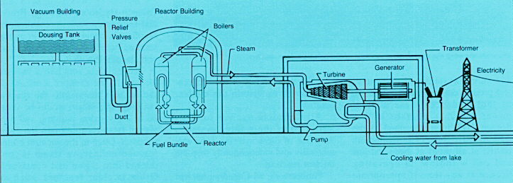
The Vacuum Building System as used in the CANDU design is described below.
 |
A single Vacuum Building is used in the CANDU plant multi-unit design. As an example, the Pickering facility has a single building for the 8 units. This model shows the structure within the Vacuum Building. This building is maintained at a vacuum relative to the pressure in any of the reactor containments. |
| Photo by J.A. Gonyeau | |
| If a large release of radioactive steam occurs in any of the containments, Pressure Relief Valves open to direct the high pressure steam to the vacuum building which includes a spray system to reduce the pressure both within the affected reactor containment and the vacuum building. Cool water sprays from sprinkler type units in the upper parts of the building to condense the steam. Refer to the figure below. | |
 |
|
| Courtesy Canadian Nuclear Association | |
 |
This photo shows the Vacuum Building (the large concrete tank behind the white water tower) as seen from the outside of the Pickering units. |
| Photo by J.A. Gonyeau |
Sample System Drawings
A typical containment spray system is illustrated below.
A typical containment ventilation system with containment fan coolers is illustrated below.
Copyright © 1996-2006. The Virtual Nuclear Tourist. All rights reserved. Revised: January 4, 2006.