Turbine Halls and
Operating Floors
The turbine operating deck differs depending on the type of
plant. In the case of the BWR design, radioactive steam passes through the
turbine, thus the turbine equipment is behind shield walls. In the case of the
PWR, CANDU, VVER, and RBMK designs, the steam passing through the turbine is not
radioactive. The photos in this section illustrate both designs.
Turbine units typically consist of a single high pressure (HP)
unit connected to 2 or 3 low pressure (LP) units in tandem. The LP turbines are
connected to the generator, which is connected to the exciter.
In many power plants the Turbine Deck has lots
of room to allow for storing the large components when the turbine is disassembled during
the outages conducted every 12-24 months. Turbines and generators are disassembled
infrequently (usually every 5 years).
PWRs, CANDU, VVER,
and RBMK
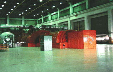
Photo by J.A. Gonyeau |
The Exciter is the nearest 'orange colored"
component. The exciter together with the rotating generator causes the generation of
electricity that then is routed through "bus bars" in air cooled piping or
"bus duct" to the Main Generator Transformer which is generally
located just outside the plant. Some electrical power is directed back to the plant for
use by plant pumps, motors, fans, etc (also called "house loads", which may be 5
% of a plant's output).
|
The cylindrical Moisture Separator can be
seen on the left hand side with the piping above going to the Low Pressure
Turbines. The moisture separators take the steam that exhausts from the High
Pressure Turbine at about 125 pound per square inch pressure and remove the
moisture in the steam so that it can be sent to the low pressure turbines.
Water removal
is important since it can cause very severe erosion of the large blades. The water used
to produce the steam must be very pure, since even trace amounts of sand or silica can
cause deposits on the blading which can damage the blading. Millions
of pounds per hour of steam passes through the turbines.
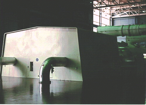 |
The high pressure turbine consists of a
very small unit located on the housing, sometimes called the "dog house". Steam
pipes are seen coming up from the floor to admit steam through the stop and governor
valves to the turbine. The piping visible in the
overhead behind the doghouse is that which goes from the moisture separators to the low
pressure turbines.
Some, but not all, power plants have windows in the
turbine hall. This plant's windows look out toward a lake that provides the cooling for
the condenser. |
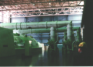 |
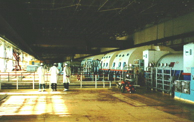
This photo shows the Turbine Hall of a U.S.
Pressurized Water Reactor facility where steam is being supplied to the Low
Pressure Turbines from the large Moisture-Separators on the
right hand side. The steam is supplied to the Moisture-separators from the exhaust of the High
Pressure Turbine. |
RBMK
 |
Turbine-generator sets usually have 2 bearings for
each major component - high pressure turbine, low pressure turbines, generator - and 1 end
bearing for the exciter. The turbines have an extensive oil system which provides
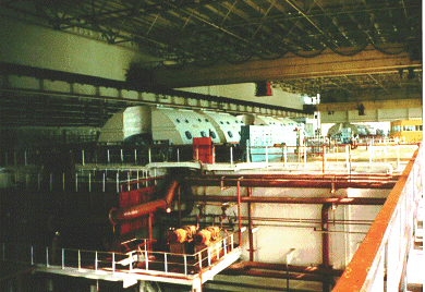
lubrication for those bearings. This picture at a RBMK
facility shows a turbine generator set with a lubricating oil system located in the pit
area below the turbine. There are usually a large storage tank, coolers to remove heat
from the oil, pumps to circulate the oil, and filters and purifiers to keep the oil clean
and free from chemical and particle impurities. |
| Photo by J.A. Gonyeau Most turbines also have a separate hydraulic oil system used for operating
the valves that admit steam to the turbine. Stop valves are either open or closed - and
are upstream from the control, governor, or throttle valves that regulate how much steam
goes to the turbine. |
 |
This photo shows one of four turbine-generators in the large Turbine hall
of a RMBK style plant. The Exciter is the closest component located in
the rectangular housing on the right hand side. The Generator is in the
cylindrical chamber. The generator produces the electricity at approximately 20, 000
volts. The generator is usually cooled by hydrogen gas, which is, in turn, cooled by sea,
lake, or river water. There are usually 2 or 3 Low Pressure Turbines in
large housings. The steam that drives the large blades is usually at a pressure of 125 to
150 pounds per square inch (psi). |
| Photo by J.A. Gonyeau At the far end
of this turbine is a small High Pressure Turbine. The steam comes
directly from steam separators that remove moisture from the steam produced in the RBMK
reactor. The steam supplied to the High Pressure Turbine is usually at a pressure of
approximately 1000 psi. Outside the United States, many power plants use two generators
per generating unit. |
BWR
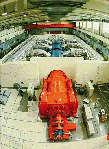 |
This photo illustrates the Turbine hall in a BWR facility. Closest to
us in the photo is the exciter, generator, 3 low pressure turbine stages,
and the high pressure turbine. On either side of the turbine can be seen
the moisture-separator reheaters.
Note the shielding around the turbine. Shielding is needed because the
steam from the BWR contains radioactive N-16, which decays with 7 second
half-life.
Courtesy KKN - Liebstadt NPP |
Copyright © 1996-2011.
Virtual
Nuclear Tourist. All rights reserved.
Revised: Saturday April 02, 2011


