Between the Condenser and Feedwater Pump, the water is called condensate; between the Feedwater Pump and the Steam Generator (or Reactor if a BWR), the water is called Feedwater.
Condensate-Feedwater Systems
The Condensate-Feedwater Systems have two major functions:
 |
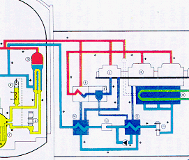
The Condensate-Feedwater System is the light blue colored
portion in the diagram. Water comes from condenser (represented by 3 pipes) to a
Condensate pump (actually 3-4), then to Low Pressure Feedwater Heaters (usually 2 sets of
3-5 heaters), then to a Feedwater pump (usually 2-3), then to the High Pressure Feedwater
Heaters (usually 2 sets of 1-2), then to the steam generators (for all types except BWR).
In that case the water is supplied to the reactor. Between the Condenser and Feedwater Pump, the water is called condensate; between the Feedwater Pump and the Steam Generator (or Reactor if a BWR), the water is called Feedwater. |
| Graphic courtesy NEK |
Major Components
Condensate Pump
Low Pressure Feedwater Heaters
Feedwater Pump

Photo by J.A. Gonyeau |
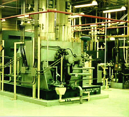
The Feedwater Pump increases the water pressure from about 350 pounds per square inch (psi) to about 1200 pounds per square inch. Each unit typically will have 2 or 3 Feedwater pumps. The feedpumps may be electrically or turbine-driven. For the pump shown, a large electric motor is located at the back.Water is being supplied by the large right hand pipe in the foreground, and leaves by the large left hand pipe. Feedpumps usually rotate at about 5000 revolutions per minute and have an oil lubricating system. Typical flowrates are 5000 to 10000 gallons per minute. |
The Feedwater Pumps take a suction from both the Condensate and Heater Drains Systems. Condensate is routed from the condenser, where the steam from the low pressure turbine is condensed to water in a vacuum. Condensate pumps raise the pressure to over 350 psi. Typically the Condensate water passes through 4 to 6 stages of heater drain coolers and feedwater heaters which recover heat from steam exhausted from the various turbine stages and heat the Condensate water temperature from 90F to approximately 350F. The condensate passes on the inside of tubes in the feedwater heaters; the heater drains pass on the outside of the tubes (shell side) of the heat exchangers.
The Feedwater pumps then raise the pressure to about 1100 psi. The water then passes typically through 1 stage of High Pressure Feedwater heater. After passing through the HP Feedwater heater, the water is at about 425F and then passes to through regulating, or control, valves and then to the steam generator in the PWR, VVER, CANDU, and RBMK designs. In the case of the BWR, the water is supplied to the reactor.
High Pressure Feedwater Heaters
Copyright © 1996-2004. Joseph Gonyeau, P.E.. The Virtual Nuclear Tourist. All rights reserved. Revised: March 15, 2001.