Emergency Electrical Systems
All nuclear plants have redundant emergency electrical systems that are designed to provide backup AC and DC power to emergency safety equipment if normal sources of electrical power are lost.
AC Electrical
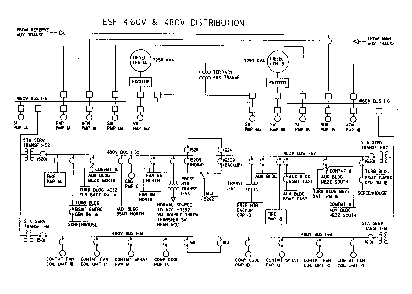
If normal AC power is lost, each diesel generator (typically a minimum of 2 per unit) starts to provide electrical power to a safeguards electrical load center (also called switchgear or bus). Diesel generators used in this application usually generate 4160 or 6900 VAC (volts AC). Each safeguards load center then supplies power directly to important electrically-driven components as:
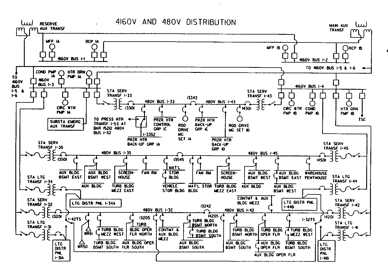
In addition, the safeguards load center supplies power to a transformer that steps down the voltage to 480 VAC to supply one or more load centers at the lower voltage. Components supplied at this lower voltage include - motor valves in safety systems, control room chillers, charging pumps, air compressors, containment cooling fans and fan cooler units.
In the event of an accident, the operating loads are stripped from the safety load center. When the diesel comes up to proper speed (~720 to 900 rpm) and appropriate voltage, a load sequencer gradually adds the loads to prevent overloading the diesel.
The following figures illustrate the configuration of typical 4160 and 480 VAC emergency electrical systems.


Diesel Generators
 |
Air start systems roll over the diesel to start it.
The diesel typically have 10 or 12 cylinders. In some
cases, a single diesel drives a single generator. In
other cases, two diesels act with opposed rotation to
drive a single generator. The latter approach is more often
used in Europe. Fuel oil is supplied to the diesel
generator from large storage tanks to provide sufficient
fuel to supply the diesel for 7 days of operation (length
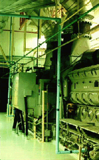
of time depends on siting of the plant). Water cooling systems cool the diesel and its lubricating oil. Fuel injectors inject fuel into the cylinders. Turbochargers are used in many diesel systems. This photo illustrates a typical diesel generator as may be found in a nuclear plant. The generator is on the far end. |
| Photo by J.A. Gonyeau |
DC Electrical
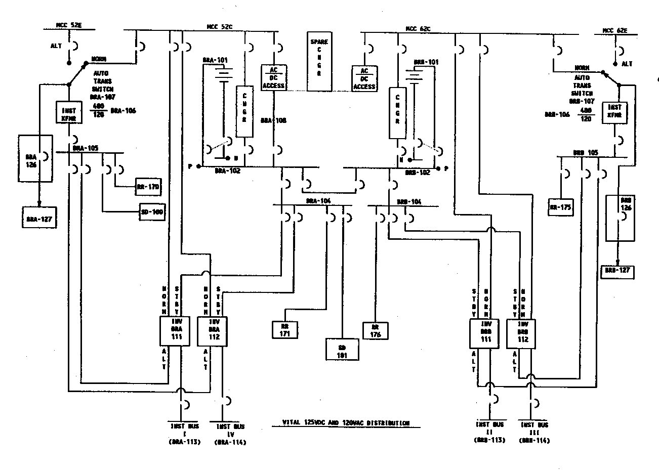
During normal and emergency conditions, the DC system supplies power to operate certain equipment so that even if no AC were available, certain safety-significant equipment would be operable. The battery source, in fact, consists of many large batteries that typically produce a nominal voltage or 125 or 240 VDC. The "battery" supplies a DC distribution panel which, in turn, supplies control power to important loads as breakers and pumps. The distribution panel is normally provided power by a battery charger. If voltage output of the battery charger drops below a certain setpoint, a switch automatically aligns the battery to be the source of power. The figure below illustrates the configuration of a typical DC system supplying a vital 120 volt AC system..

Copyright © 1996-2006. The Virtual Nuclear Tourist. All rights reserved. Revised: January 4, 2006.