BWR Plant Photos - inside and outside
Boiling Water Reactors (BWRs) currently operating in the United States were designed and manufactured by General Electric. Generator outputs are typically rated between 550 and 1100 MWe. The generator output is typically 1/3 of the reactor's thermal output.. The following photos and graphics illustrate the equipment representative of the BWR plant. Contributors include CP&L, TVA, General Electric, KKN, Niagara Mohawk, and Detroit Edison.
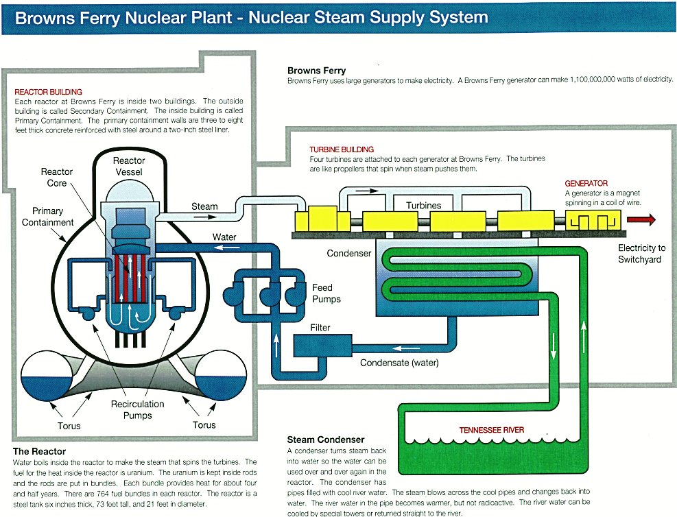
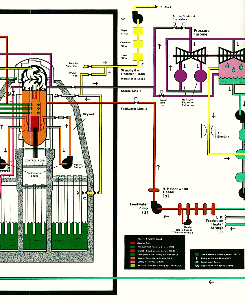
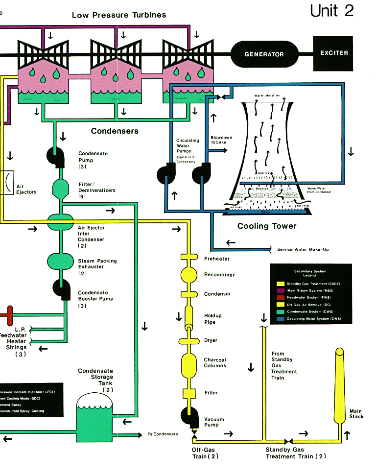
Overview
Three plant cycles of a BWR (189K); Color coding of equipment based on system (42K)
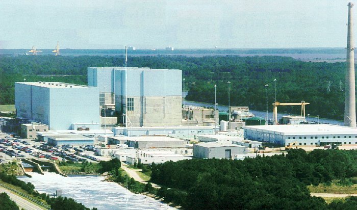
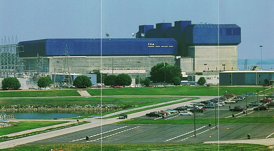
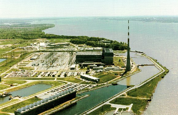
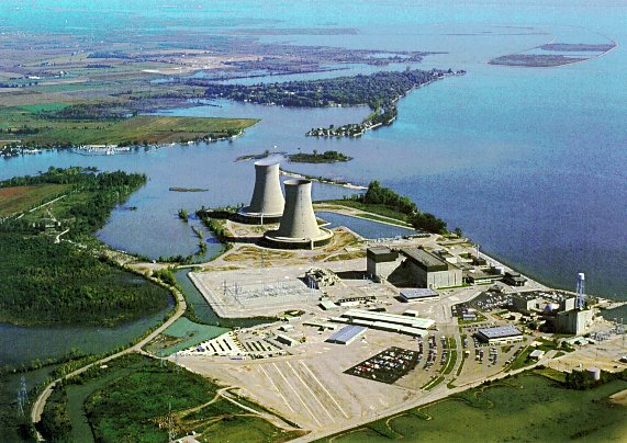
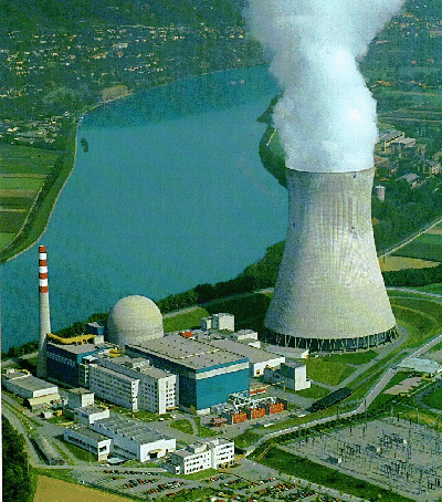
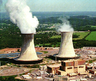
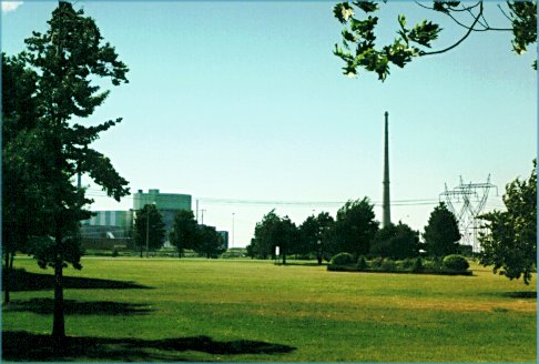
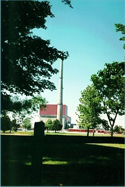
Outside Plant Views
Different views of Brunswick (82K - 124K - 92K); Browns Ferry - main plant (162K) - overview (80K); Fermi Site Overview (83K); Leibstadt plant with natural draft cooling tower (160K); Limerick plant with natural draft cooling tower (111K); Nine Mile Point 2 (42K); Fitzpatrick (31K)
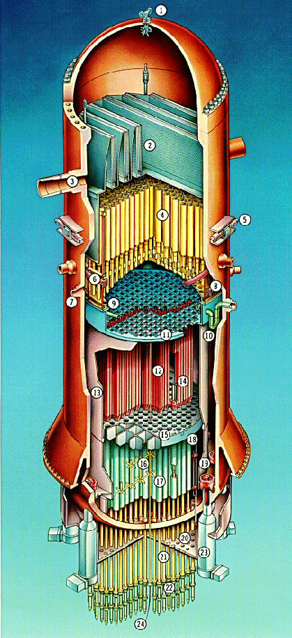
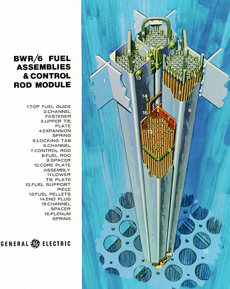
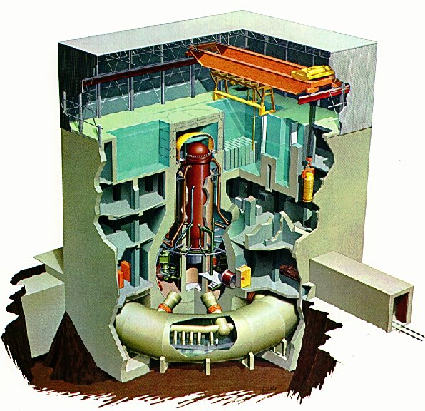
Reactor
BWR reactor illustration (275K); Fuel assembly with legend (192K); Inspecting a BWR fuel assembly (43K); GE Fuel Assembly - partial view (62K). A sketch illustrating the
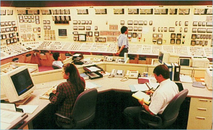
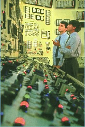
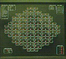
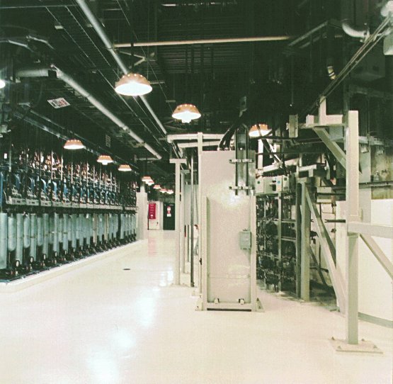
Control rooms
Control Room (98K); Control Room (41K); Core layout showing control rods on control panel (46K)
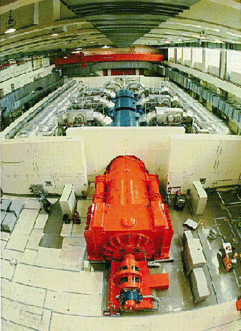
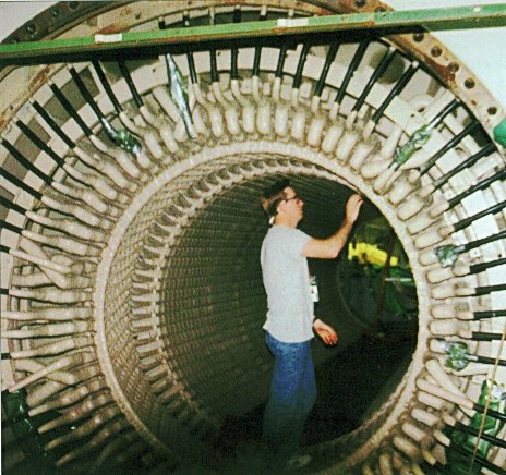
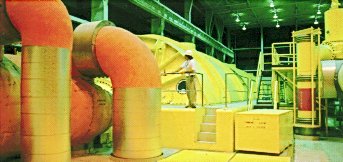
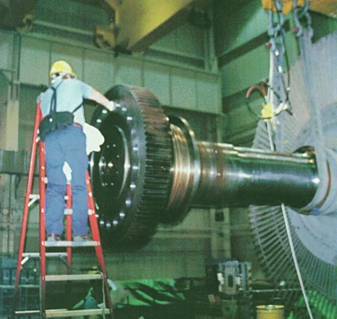
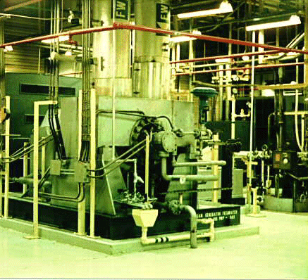
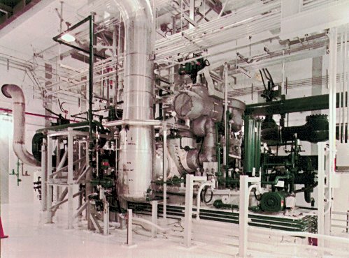
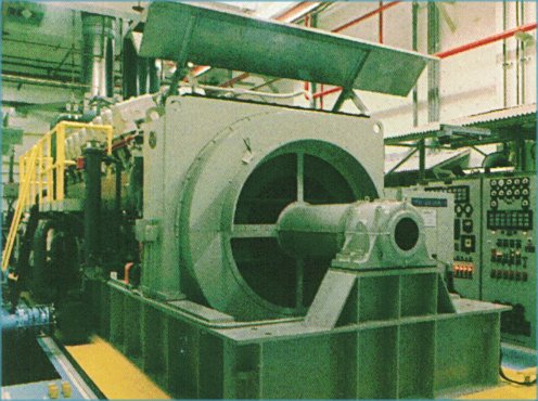
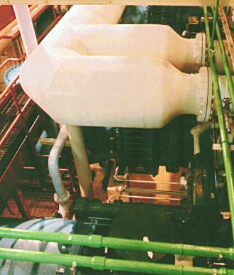
Turbine Generator Equipment
Turbine-generator showing shielding (148K); Inside the stationary part of the generator (78K); Turbine during operation (20K); Disassembly of a turbine during an outage (53K); Looking from generator end (49K); steam driven main feedwater pump (160K); main generator transformer (92K). One sketch (219K) shows the flow paths between the reactor, turbine, and feedwater systems. Another sketch (133K) illustrates the turbine, generator, condenser, and traditional power plant systems.
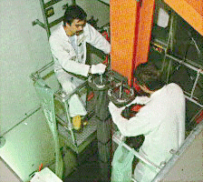
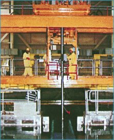
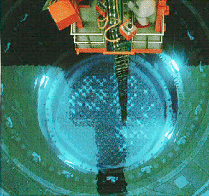
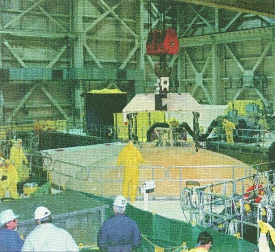
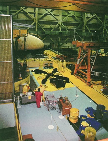
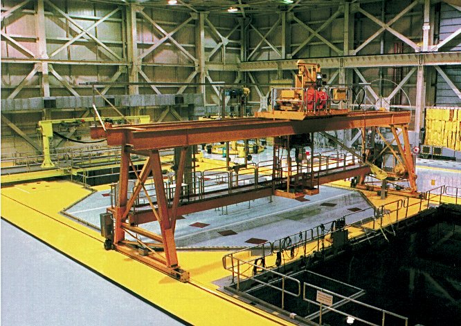
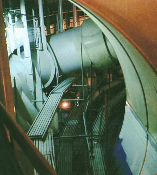
Refueling activities
Fuel handling activities during outage (23K); BWR core during refueling showing blue glow from Cerenkov radiation (79K); Typical Reactor Building layout (106K); Reactor vessel head being lifted (85K); Refueling floor during outage after reactor vessel head has been removed . Note boundary between areas (85K); Refueling floor during operation (120K)
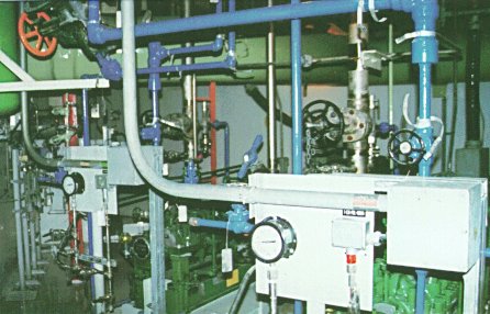
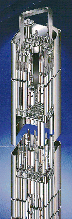
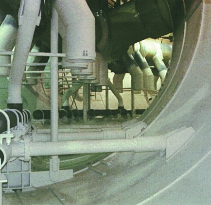
Reactor Support Equipment
Control rod drive actuators used to drive the control rods into the reactor (69K). A sketch (249K) illustrates the drywell, major equipment, and ventilation support systems.
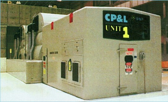
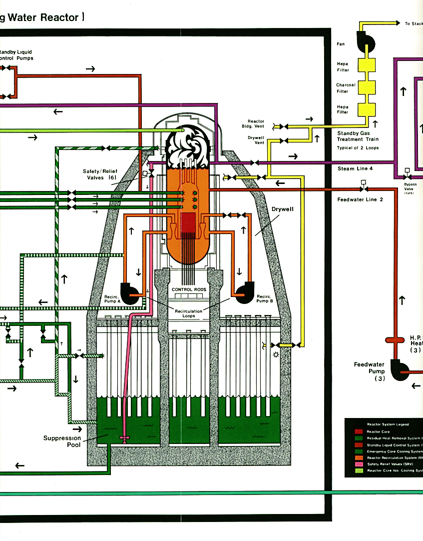
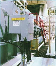
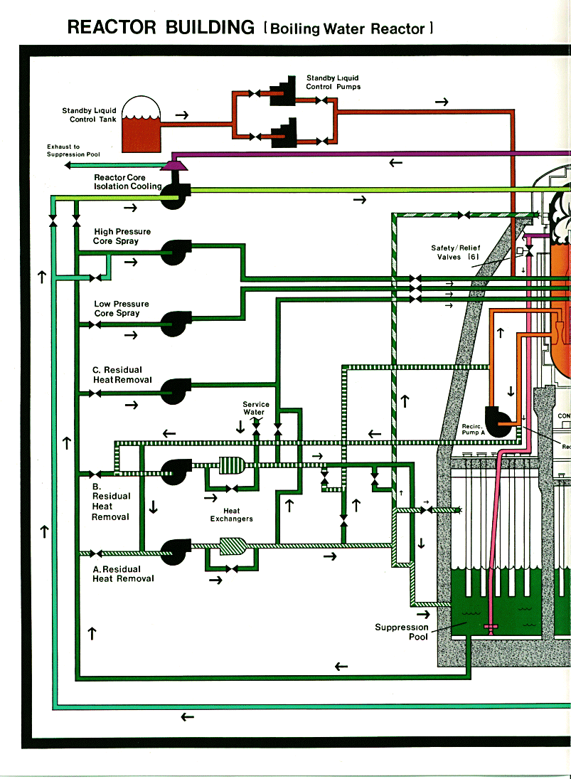
Emergency Systems
HPCI pump used for high pressure emergency coolant injection to the reactor, this pump is turbine driven by steam (62K); Diesel Generator (20K); Diesel Generator (54K); Torus (this large tank surrounding the drywell containing the reactor) is normally half-full of water. The photo shows the downcomer where water/steam is discharged if there is a major piping break in the drywell. Also, relief valves discharge through these pipes. (48K) Torus showing piping between containment and torus (63K). Sketch (193K) illustrating relationship and flow paths for major emergency systems - Residual Heat Removal, High Pressure Core Spray, Low Pressure Core Spray, Reactor Core Isolation Cooling, Standby Liquid Control, Suppression Pool, Safety/Relief valves.
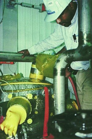
Training Activities
Simulation of performing maintenance on a pump in a radiation controlled area (45K); Maintenance workers training inside recirculation pump mockup (25K)
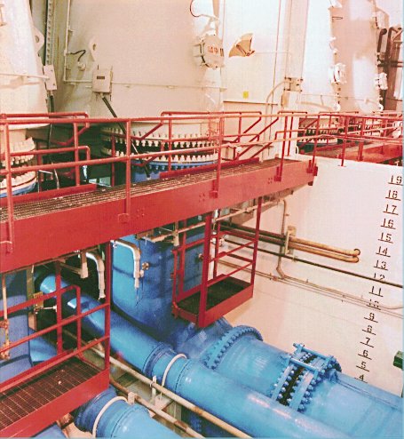
Circulating Water System
Circulating water piping (35K); Circulating water piping (69K)
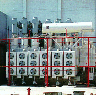
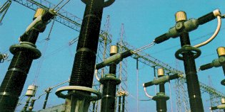
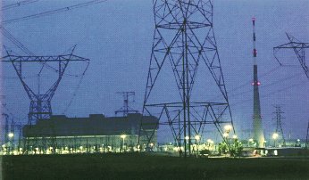
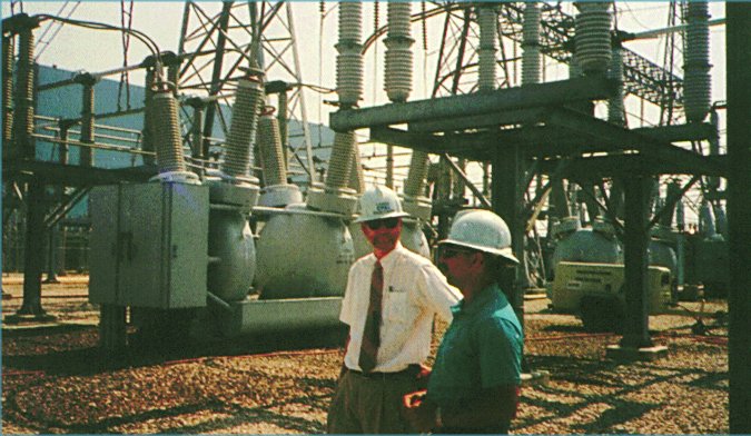
Substations
Substation buswork (19K); Substation at night (20K); Substation (85K)
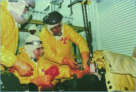
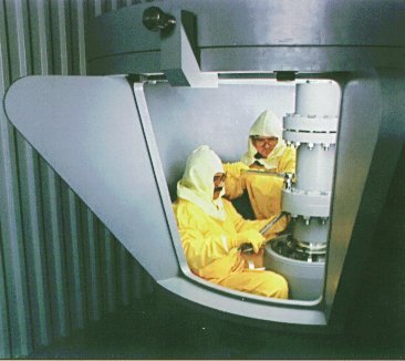
Radiation Protection
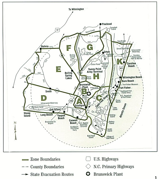
Emergency Planning zones around plant (114K); Checking the radiation protection isolation glove bag around a valve prior to starting work (39K)
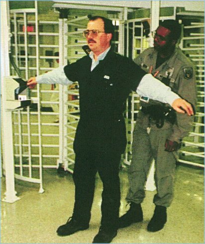
Security
Hands-on frisk when one does not pass the metal or explosives detector tests (65K)
Copyright © 1996-2004. Joseph Gonyeau, P.E.. The Virtual Nuclear Tourist. All rights reserved. Revised: September 14, 2001.